![]()
![]()
![]()
![]()
![]()
|
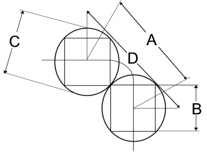
LOAD CLEARANCE CHART – HORIZONTAL CURVES |
||||
 |
||||
| Sprocket Diameter |
“A” Load Spacing |
“B” Square Max. |
“C” Round Max. |
“D” Curve |
| 15-1/4” | 12” | 7-9/16” | 10-3/4” | 12” |
| 24” | 13-5/8” | 19-1/4” | ||
| 36" | 19-5/8” | 27-3/4” | ||
| 22-15/16” | 12” | 8-1/16” | 11-3/8” | 18” |
| 24” | 14-1/2” | 20-7/16” | ||
| 36" | 20-7/16” | 28-15/16” | ||
| 30-9/16” | 12” | 8-1/4” | 11-11/16” | 24” |
| 24” | 15-15/16” | 21-5/8” | ||
| 36" | 21-1/4” | 30-1/16” | ||
|
NOTES: Cableway Conveyor Menu Anatomy |
||||