|
The
typical Cableway Conveyor system is much like an “erector set” in which few
components can be utilized to form almost any configuration imaginable. By using
idle corners, vertical curves, and quick dips, a Cableway system can be
customized to compliment operation. Small radius turns allow the Cableway system
to be utilized in tight production areas that might otherwise be inaccessible to
floor conveyors or other types of material handling equipment.
The
sample below depicts a typical Cableway Conveyor system:
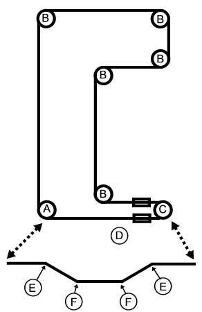
The Typical Cableway
Conveyor system consists of track, trolleys, cable, drive corners, idler
corners, dip sections, vertical curves, track adjusters, and trolley fittings.
Following
is a brief description of each of the major components:
- Track:
Trolleys ride on an inverted tee rail complete with hanger brackets for
suspension and end brackets for splicing rail into a continuous rail system.
- Cable: The
standard cable used on AOC Cableway Conveyors is a pre-stretched 1/4"
or 3/8" diameter, 7 X 19 stranded core, galvanized, aircraft quality
cable. The standard galvinized cable is equipped with pressed on (swagged)
galvanized driving lugs on 12" centers.
Cable elongation is minimized by the use of pre-stretched aircraft cable
with a safety factor of 8 to 1 (based ultimate strength).
- Trolleys:
Cableway trolleys are fabricated for strength, interchangeability, and
economy. Trolley side plates made of heavy gauge pressed steel, zinc plated
for maximum corrosion resistance. Trolley wheels are supplied for loads
ranging from 80 to 125 lbs. (per trolley) and with lubrication fittings and
bearings selected to meet varying operating conditions.
-
Cable:
The standard cable used on AOC Cableway Conveyors is a pre-stretched ¼”
or 3/8” diameter, 7 x 19 strand core, galvanized, aircraft quality cable.
The standard galvanized cable is equipped with pressed on (swaged)
galvanized driving lugs on 12” centers.
Cable elongation is minimized by use of pre-stretched aircraft cable with a
safety factor of 8 to 1 (based ultimate strength).
- (A) Drive:
The AOC standard drive unit is a complete component and is furnished as
either a 90º or 180º corner with
sprocket diameters of 15-1/4”, 22-15/16”, or 30-9/16”.
The endless cable is pulled through the rail by a cast iron drive sprocket
riding on a rugged anti-friction roller bearing. Sprockets have slots that
mesh with trolley/cable lugs, which propel the trolley/cable through the
rail system.
- (B
and C) Idler
Corner: Idler corners
are used on all horizontal curves. Idler corners align and guide the cable
and trolleys through horizontal curves. The corners are constructed of heavy
gauge steel members incorporating a section of inverted curve tee track.
Cast iron sprockets with rugged anti-friction bearings are mounted to the
idler corner frame. Idler corners are available in diameters of 15-1/4”,
22-15/16”, and 30-9/16” for ¼” diameter cable. 22-15/16” diameter
sprockets only are available for 3/8” cable.
- (E, F and G) Vertical Curves:
Loads can be transported from one elevation to another by using vertical
curves. This feature allows loads to be transported from floor level to
overhead, from first floor to second or third floor, and from one building
to another. Vertical curves also can be used to dip loads in vats for
chemical treating, painting, etc.
A typical elevation requires a minimum of two vertical curves. Top and
bottom vertical curves are constructed of standard tee track bent to the
required radius and arc. The top and bottom curves are normally fabricated
in two sections, on systems with minimal inclines. Systems requiring long
inclines will consist of two vertical curves and a straight track section.
The use of two-piece or three-piece curves is predicated only by the
physical size of the incline.
- Quick Dip (not
pictured):
Quick Dip corners are similar to bottom vertical corners except for the fact
that they allow a load to be quickly lowered and raised. The quick dip is
primarily utilized when a load must be lowered into a tank and immediately
removed. Quick dips are constructed of a rigid steel frame complete with tee
track and rotating idle sprockets. The section is very similar to a
horizontal idle curve except that it mounts vertically in lieu of
horizontally.
-
Track
Adjusters: Track adjusters are used
to adjust track length in order to make up slack in the cable system. The
adjusters are typically mounted at a 180º
turn on the “slack side” of a system.
-
Inline Take Up (D):
Track
adjusters are used to adjust the track length in order to make up slack in
the cable system. The adjusters are typically mounted at a 180º turn on the
"slack side" of the system
Cableway
Conveyor Menu
Anatomy
Cableway
Conveyor Calculation and Design - 4 Steps
Technical
Data
Sample
Cableway Line Pull Calculation
Questions
that need to be answered for your Cableway System
Drive
Selection
Track and
Fittings
Trolleys
Trolley
Attachments
Load
Clearance Chart - VERTICAL CURVES
Load
Clearance Chart - HORIZONTAL CURVES
Drive
Units
Idler
Corners
Vertical
Curves
Vertical
Dip
General
Data
|